Three.js Rendering Pipeline Demo
About the Project
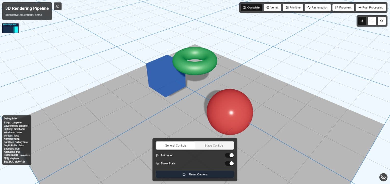
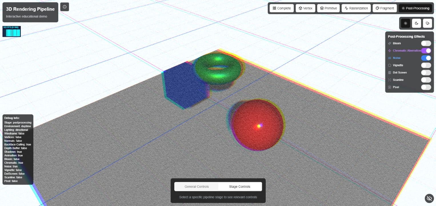
An interactive educational visualization of the 3D graphics rendering pipeline implemented using Three.js and React. This project provides a comprehensive visualization of the modern 3D graphics rendering pipeline. It allows users to explore each stage of the pipeline interactively, helping to demostrate the complex processes that transform 3D data into 2D images on your screen.
Screenshots
Role(s) and Responsibilities
Full Stack Developer & Graphics Programmer
As the sole developer on this project, I was responsible for:
- Designed and implemented complete 3D rendering pipeline visualization system
- Developed custom GLSL shaders to showcase various rendering stages
- Implemented user interface providing interactive controls and educational annotations
Project Features
Interactive Learning Tool
This project serves as an educational tool for understanding the 3D graphics rendering pipeline. It visualizes the transformation of 3D data to 2D screen images through:
- Interactive Pipeline Visualization: Step through each stage of the rendering pipeline
- Multiple Rendering Stages: Vertex, Fragment, Geometry, Rasterization, and Complete Rendering
- Environment Settings: Switch between daytime, nighttime, and rainy environments
- Lighting Models: Toggle between Phong and PBR (Physically Based Rendering) shading models
- Real-time Parameter Adjustments: Modify lighting parameters, camera position, and model properties
Technical Implementation Highlights
Graphics Rendering Pipeline Overview
The 3D graphics rendering pipeline is a sequence of stages that transforms 3D scene data into a 2D image. The main stages are:
- Vertex Processing: Transforms vertices from 3D object space to 2D screen space
- Geometry Processing: Handles primitive assembly, clipping, and culling
- Rasterization: Converts vector information to pixels (fragments)
- Fragment Processing: Determines the color of each pixel through lighting calculations and texturing
- Output Merging: Combines fragment colors with the frame buffer
Vertex Stage Visualization
The implementation shows how vertices are processed before rendering. Users can observe:
- Model, view, and projection transformations
- Vertex shader operations
- Wireframe representation of the geometry
vertexShader: `
  varying vec2 vUv;
  void main() {
    vUv = uv;
    gl_Position = projectionMatrix * modelViewMatrix * vec4(position, 1.0);
  }
`
Geometry Processing
This stage demonstrates:
- Primitive assembly (how vertices form triangles)
- Back-face culling
- Clipping against the view frustum
// PrimitiveVisualization component applies these materials
const material = new THREE.MeshBasicMaterial({
  color: wireframe ? 0x00ff00 : 0xffffff,
  wireframe: wireframe,
  side: backfaceCulling ? THREE.FrontSide : THREE.DoubleSide,
  vertexColors: false,
  transparent: true,
  opacity: wireframe ? 0.8 : 1.0,
})

// For non-wireframe mode, we create a checkerboard pattern
// by assigning alternating colors to triangles
if (!wireframe) {
  const colors = []

  // Alternating colors for triangles
  for (let i = 0; i < positionAttribute.count; i += 3) {
    const color = i % 6 === 0 ? new THREE.Color(0xff5555) : new THREE.Color(0x55ff55)
    colors.push(color.r, color.g, color.b)
    colors.push(color.r, color.g, color.b)
    colors.push(color.r, color.g, color.b)
  }

  geometry.setAttribute("color", new THREE.Float32BufferAttribute(colors, 3))
  material.vertexColors = true
}
Rasterization Stage
Visualizes how geometric primitives are converted to fragments (potential pixels):
- Triangle traversal
- Perspective-correct interpolation
- Screen-space transformation
// Rasterization stage pixel visualization shader
fragmentShader: `
  uniform float time;
  varying vec2 vUv;

  void main() {
    // Create pixelated effect
    float pixelSize = 0.05;
    vec2 pixelatedUV = floor(vUv / pixelSize) * pixelSize;

    // Add grid pattern
    float gridLine = step(0.98, mod(vUv.x / pixelSize, 1.0)) +
                    step(0.98, mod(vUv.y / pixelSize, 1.0));

    // Base color based on UV coordinates
    vec3 color = vec3(pixelatedUV.x, pixelatedUV.y, sin(time) * 0.5 + 0.5);

    // Apply grid lines
    color = mix(color, vec3(0.0), gridLine);

    gl_FragColor = vec4(color, 1.0);
  }
`
Fragment Stage
Shows the pixel-level operations:
- Texture sampling
- Color computation
- Lighting calculations (Phong model and PBR)
- Material properties application
// Fragment stage shader with quadrant visualization
fragmentShader: `
  uniform float time;
  varying vec2 vUv;
  varying vec3 vNormal;
  varying vec3 vPosition;

  void main() {
    // Split the view into quadrants
    vec2 quadrant = step(vec2(0.5), vUv);
    float quadrantIndex = quadrant.x + quadrant.y * 2.0;

    vec3 color;

    // Quadrant 0: Base color (bottom-left)
    if (quadrantIndex < 0.5) {
      color = vec3(0.8, 0.8, 0.8);
    }
    // Quadrant 1: Normal map (bottom-right)
    else if (quadrantIndex < 1.5) {
      color = vNormal * 0.5 + 0.5;
    }
    // Quadrant 2: Roughness/metalness (top-left)
    else if (quadrantIndex < 2.5) {
      // Simulate roughness/metalness map
      float roughness = mod(vPosition.x * 10.0 + vPosition.y * 10.0 + vPosition.z * 10.0, 1.0);
      float metalness = sin(vPosition.x * 50.0 + time) * 0.5 + 0.5;
      color = vec3(roughness, metalness, 0.0);
    }
    // Quadrant 3: Lighting calculation (top-right)
    else {
      // Simple lighting calculation
      vec3 lightDir = normalize(vec3(sin(time), 1.0, cos(time)));
      float diffuse = max(dot(vNormal, lightDir), 0.0);
      vec3 baseColor = vec3(0.8, 0.8, 0.8);
      color = baseColor * diffuse;
    }

    // Add grid lines to separate quadrants
    float gridLine = step(0.98, mod(vUv.x, 0.5)) + step(0.98, mod(vUv.y, 0.5));
    color = mix(color, vec3(1.0), gridLine);

    gl_FragColor = vec4(color, 1.0);
  }
`
Custom GLSL Shader Implementation
This project extensively utilizes GLSL (OpenGL Shading Language) to create custom visual effects for each pipeline stage. GLSL allows us to directly program the GPU, providing both educational insight and visual fidelity.
Fragment Visualization Quadrant Shader
// Vertex shader
varying vec2 vUv;
varying vec3 vNormal;
varying vec3 vPosition;

void main() {
  vUv = uv;
  vNormal = normalize(normalMatrix * normal);
  vPosition = position;
  gl_Position = projectionMatrix * modelViewMatrix * vec4(position, 1.0);
}

// Fragment shader
uniform float time;
varying vec2 vUv;
varying vec3 vNormal;
varying vec3 vPosition;

void main() {
  // Split the view into quadrants
  vec2 quadrant = step(vec2(0.5), vUv);
  float quadrantIndex = quadrant.x + quadrant.y * 2.0;

  vec3 color;

  // Quadrant 0: Base color (bottom-left)
  if (quadrantIndex < 0.5) {
    color = vec3(0.8, 0.8, 0.8);
  }
  // Quadrant 1: Normal map (bottom-right)
  else if (quadrantIndex < 1.5) {
    color = vNormal * 0.5 + 0.5;
  }
  // Quadrant 2: Roughness/metalness (top-left)
  else if (quadrantIndex < 2.5) {
    // Simulate roughness/metalness map
    float roughness = mod(vPosition.x * 10.0 + vPosition.y * 10.0 + vPosition.z * 10.0, 1.0);
    float metalness = sin(vPosition.x * 50.0 + time) * 0.5 + 0.5;
    color = vec3(roughness, metalness, 0.0);
  }
  // Quadrant 3: Lighting calculation (top-right)
  else {
    // Simple lighting calculation
    vec3 lightDir = normalize(vec3(sin(time), 1.0, cos(time)));
    float diffuse = max(dot(vNormal, lightDir), 0.0);
    vec3 baseColor = vec3(0.8, 0.8, 0.8);
    color = baseColor * diffuse;
  }

  // Add grid lines to separate quadrants
  float gridLine = step(0.98, mod(vUv.x, 0.5)) + step(0.98, mod(vUv.y, 0.5));
  color = mix(color, vec3(1.0), gridLine);

  gl_FragColor = vec4(color, 1.0);
}
Pixelation Rasterization Shader
// Vertex shader
varying vec2 vUv;
void main() {
  vUv = uv;
  gl_Position = projectionMatrix * modelViewMatrix * vec4(position, 1.0);
}

// Fragment shader
uniform float time;
varying vec2 vUv;

void main() {
  // Create pixelated effect
  float pixelSize = 0.05;
  vec2 pixelatedUV = floor(vUv / pixelSize) * pixelSize;

  // Add grid pattern
  float gridLine = step(0.98, mod(vUv.x / pixelSize, 1.0)) +
                  step(0.98, mod(vUv.y / pixelSize, 1.0));

  // Base color based on UV coordinates
  vec3 color = vec3(pixelatedUV.x, pixelatedUV.y, sin(time) * 0.5 + 0.5);

  // Apply grid lines
  color = mix(color, vec3(0.0), gridLine);

  gl_FragColor = vec4(color, 1.0);
}
Integration with Three.js
// Example from RasterizationVisualization
const pixelMaterial = new THREE.ShaderMaterial({
  uniforms: {
    time: { value: timeRef.current },
  },
  vertexShader: `
    varying vec2 vUv;
    void main() {
      vUv = uv;
      gl_Position = projectionMatrix * modelViewMatrix * vec4(position, 1.0);
    }
  `,
  fragmentShader: `
    uniform float time;
    varying vec2 vUv;

    void main() {
      // Create pixelated effect
      float pixelSize = 0.05;
      vec2 pixelatedUV = floor(vUv / pixelSize) * pixelSize;

      // Add grid pattern
      float gridLine = step(0.98, mod(vUv.x / pixelSize, 1.0)) +
                      step(0.98, mod(vUv.y / pixelSize, 1.0));

      // Base color based on UV coordinates
      vec3 color = vec3(pixelatedUV.x, pixelatedUV.y, sin(time) * 0.5 + 0.5);

      // Apply grid lines
      color = mix(color, vec3(0.0), gridLine);

      gl_FragColor = vec4(color, 1.0);
    }
  `,
  side: THREE.DoubleSide,
})